Abstract
Barahat Al Nouq is the central square of the heart of Doha, the capital of Qatar. Following traditional Arabic architecture, the new roof construction is reinterpreting ancient building elements which already functioned as adaptive and responding. This is also the case with the new retractable roof with its movable membrane-covered shading panels.
Barahat Al Nouq
Qatar has recognized the need to establish a clear cultural identity expressed through adequate urban planning architecture. Msheireb Heart of Doha is one of the flagship projects designed by the architects Mossessian & Partners [1]. It tries to achieve this by regenerating and at the same time preserving the historical centre of Doha. Barahat Al Nouq central square is the main public space of this development and is designed as an urban room functioning as a multi-purpose meeting space that comprises nine mixed-use, residential, commercial, and retail buildings surrounding a major public square at the heart of the Msheireb. It is conceived as the ‘urban majlis’ – a room where visitors to Msheireb are welcomed and received [2].
Drawing on the traditional majlis, Barahat Al Nouq is ordered, simple, and elegant. Hosts and guests are seated on the cushioned floor around the perimeter that is edged by a highly ordered colonnade where people can enjoy the perimeter restaurants and cafes. Reflected light through the traditional malqaf (in Arabic: wind-catcher) is reinterpreted in the form of a suspended, retractable roof where natural light is filtered to reduce solar transmission and to allow significant cooling.
In Doha, daytime temperatures easily rise to 50°C. The concept of Barahat Al Nouq is to limit temperatures to below 32°C. This is achieved by a shading combination of the retractable roof 30 m above ground together with conventional membrane canopies on the ground.
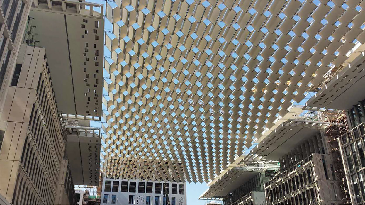
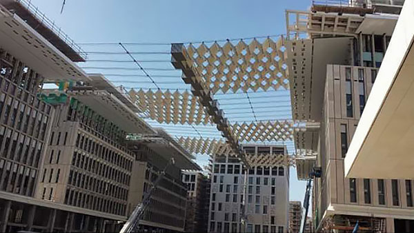
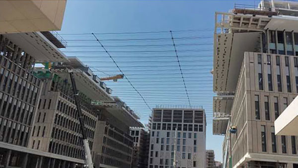
Figure 1 View from Barahat Al Nouq square against un-folded roof structure
Structure
The moveable roof consists of 1080 individual membrane-covered frame modules suspended on 60 structural cables that span the rectangular 35 m wide square; the length of the square is 90 m. The cables are anchored in the roof area of the six buildings located at both ends of the square. The storage of the membrane elements are also located here. The elements are stored vertically and folded in packages.
The membrane module itself is a rectangular shading element; outer dimensions are approximately 2,70 m x 1,40 m. It consists out of an aluminum profile that is double-sided and is covered with a PVC membrane. Each module is suspended from a moving beam, the so-called “sliding trolley”, that runs along a pair of structural cables.
Using electric driven winches, traction cables pull the first trolley along these structural cables towards the opposite side of the building. This leads to an “accordion-like” un-folding of all membrane elements as the panels are hinged with each other. The membrane structure can now be placed above the square either aligned or in offset, so called shifted position. Interacting with neighboring membrane elements, different ceiling patterns can be created. These depend mainly on the position of the sun.
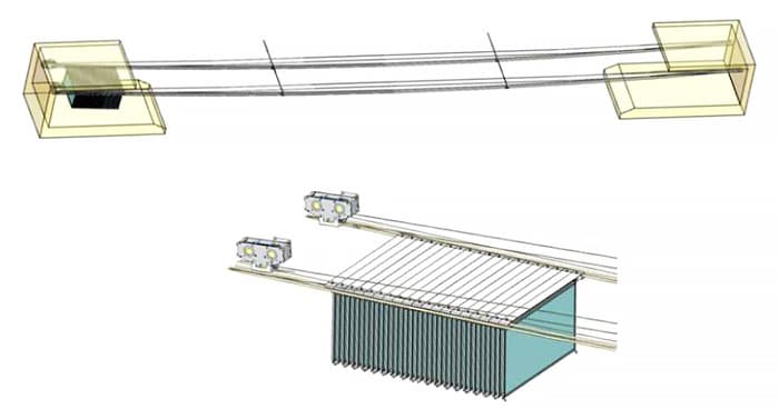
Figure 2 (a) axis with one pair of structural cables and suspended membrane panels parked in the roof garage (b) suspended membrane panel
Construction Elements
The entire system consists of 26t of structural cables, 10.000m² of PVC membrane, 150t of steel, 58t of aluminum, 30 motors, and 60 winches.
Before any of these elements could be installed, the whole system was checked using a “mock-up” in Memmingen, Germany. The performance, design, and feasibility of this unique structure were checked. 1/10 of the entire system was built at the Pfeifer headquarters, recycling the steel of the temporary scaffolding structure which supported the huge Durban stadium arch in South Africa during erection. The success of this prototype was both a requirement and motivation for realizing the structure in the heart of Doha.
Anchoring
While the structural concrete works continued, Pfeifer monitored and surveyed the casting of the steel tubes in the roof area. They were later used to attach an anchor system for cables taking forces up to 600kN. To achieve dimensional accuracy, four steel tubes with a diameter of 100mm each were set into the 800 mm thick concrete walls. Threaded rods (M36) were then inserted into these empty tubes so that the anchoring base plates could be fixed to the structural steel. An installation accuracy of less than 5 mm was achieved because enough space for rod adjustment was allowed inside the bigger steel tubes. Such precision was an absolute prerequisite for the cable installation. Placing them in the correct position was ensured that the cables were loaded precisely with the defined pretension values.
Cables, Springs, and Catenaries
Thirty pairs of horizontal cables are distributed along the entire length of the square spanning 35 m from the building roof to the opposite side of the square. They were designed using the properties of 35mm diameter fully locked cables applied with an initial pre-stress of around 80kN. This maintained the deflection of the cables, under the dead load of the panels, at 1000 mm at the centerline. The cables themselves were anchored to 6 independent buildings located on the north and south sides of the square.
Between adjacent buildings on the same side of the plaza, the primary cables were supported by a catenary element connected to a compression strut that was pinned to each building. This allowed primary cable axis forces to be carried towards the building structure.
Each of the structural cables was anchored to one of the above-mentioned anchor plates. In addition, a secondary structural compression spring was installed on one end of the cable. This spring is necessary to limit the maximum forces in the cable, which in turn limits forces in the building. It protects the structure against high accidental force overload by allowing the primary cables to be extended. Adjustment of the length of the cable over its lifetime is also possible because of the effects of cable creep and concrete creep in the buildings. The stiffness of the compression spring is around 9kN/m.
Tie Bar System
A tie bar system was added perpendicular to the structural cables. This stabilizes the whole cable structure against unevenly distributed loads which may occur when opening the roof. Each tie bar system is clamped so that the structural cables are divided into three equal parts. These cross-connections reinforce every single cable and reduce its deformation under load.
Flag Pole
To prevent torsion in the cable so-called “flag poles” were installed. The flag pole is located close to the compression spring inside the membrane panel garage. The pole is suspended vertically from the cable and is fixed to it by a steel clamp on its top side. The bottom part of the pole is hinged to the building roof to block the rotation of the cable around its own axis.
Membrane Panels
The primary construction of the membrane panels is made up of four aluminum profiles. The upper, horizontal frame profile and both vertical ones can be bolted together. The lower horizontal beam is a sliding element that is inserted between vertical ones from below. This way the membrane can be inserted and then tensioned easily.
The downward-facing membrane panel is a white-colored PVDF coated polyester fabric – Ferrari 1002 Fluortop T. The same quality is used for the upper panel but in a golden color in order to maximize the solar reflection property of the entire roof system. In combination, both membrane layers can reduce the light transmission to nearly zero.
Upper and lower membrane panels were fabricated by Pfeifer Covertex, in our fabrication plant in Shanghai. On-site, they were pre-assembled with keder profiles on all of the edges so that they could be clipped into the main frame profile. Afterward, the lower horizontal beam was screwed down into its final position. In this way, pre-tension is introduced into the membrane panels and the flat membrane surfaces are stretched nicely and wrinkle-free. The final step of the panel assembly was the fixing of corner reinforcement plates, an outer edge cover, and the panel hinges for suspension.
Sliding Trolleys
The readily assembled membrane panels were lifted onto the roof of the buildings. The first panel was connected to the first sliding trolley spanning a pair of structural cables. These trolleys are equipped with a PTFE sliding surface that allows them to run along the structural cables. The second panel was connected to the adjacent trolley and hinged together with the first panel underneath. In this way, a pair of membrane panels was created that un-folds in a V-shape as it slides along the structural cables. Each axis of folding membrane panels consists of 18 V-shaped folds. The sliding trolleys are linked together with a set of stainless steel tie cables, limiting the distance to which one individual V-shaped fold can open.
Driving Mechanism
Only the first trolley at each axis is connected with two drive cables. These cables are connected to “drive through” motor winches that are stored in the garage. They are also looped around a sheave on the opposite side of the square. By winding of the upper or lower drive cable winch, the membrane panels can either be retracted by pulling the first trolley and pushing the rest backwards into the garage or extended across the Barahat square by pulling the first trolley which then tows the other panels behind it.
By using this mechanism, the panel patterns when open or closed can differ in order and design. When open, each axis is adjustable in “offset” or “aligned” roof shade position. Panels can also be “parked” in either flat, unfolded, or in a V-shaped half-folded. Due to the arrangement of the supporting buildings, there are 5 garages in total, positioned on both sides of the square storing the 1080 membrane elements. These are grouped into 30 lines, each line equipped with 36 panels.
Driving Control
Normally, the roof will be closed in the morning to give shade during the daytime and opened during nighttime. The whole opening or closing process takes about 5 minutes, but this is subject to several conditions that are automatically checked by around 700 different sensors.
These are, for example, weather and temperature, the strength of the electric current, the position of membrane elements, fire detection, or access control to the building roof and garages. Only if all sensors send trouble-free signals can the roof be moved.
With regard to wind, the following rules apply:
- The roof can only be extended manually if the wind speed is below 10m/s during the moving process. It can be manually retracted in a wind speed of up to 21m/s.
- The roof will be automatically stored in the garage if the wind reaches speeds of 21m/s or more in gusts. Statistically, this happens once a week.
- No major damage will occur if the roof is accidentally exposed to wind gusts of 25m/s. Statistically, this occurs once a month.
Conclusion
The retractable Barahat Al Nouq was completed in July 2015 after intensive planning, fabrication, and a four-month installation period.
The result of our work is a roof that incorporates adjustable and movable technology that can adapt to variations in climate and to the position of the sun. These kinetic elements were already used in traditional Arabic architecture like the “malqaf” and have now been reinterpreted in the form of this suspended roof.
Adaptive and kinetic building elements are new ways by which architecture has re-detected over recent decades to respond to changing environmental conditions that affect building performance and the comfort of the people in them. The retractable Barahat Al Nouq roof does this.
Membrane structures benefit from this trend because fabric and foil provide excellent material properties that match the needs of kinetic systems; lightness, flexibility, and adaptiveness. We will continue to explore the possibilities of this technology and look forward to new projects that allow us “to bring technology into application”.
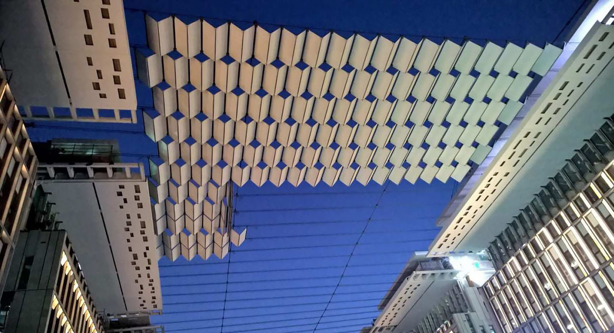
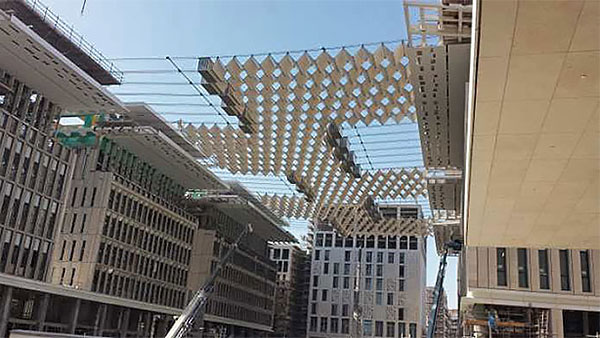
Figure 3 Unfolded membrane panels during installation
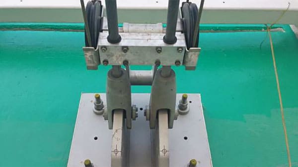
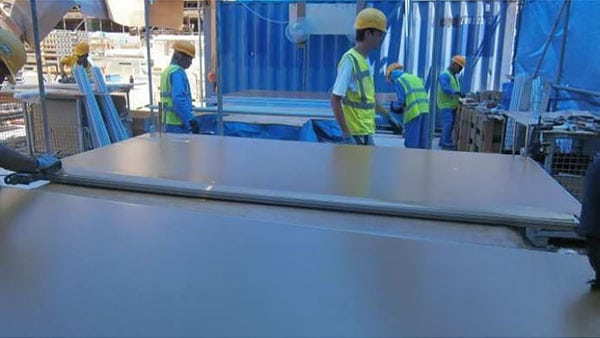
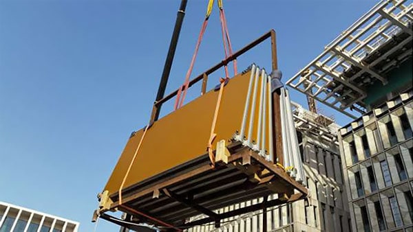
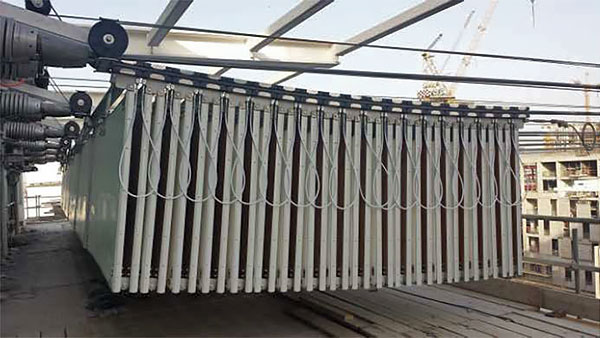
Figure 4 (a) Anchor plate with structural cable attached (b) Installation of first cable (c-d) Fabrication of membrane panel (e,f) Lifting and installation of membrane panels (g,h) Membrane panels stored in roof garage
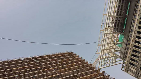
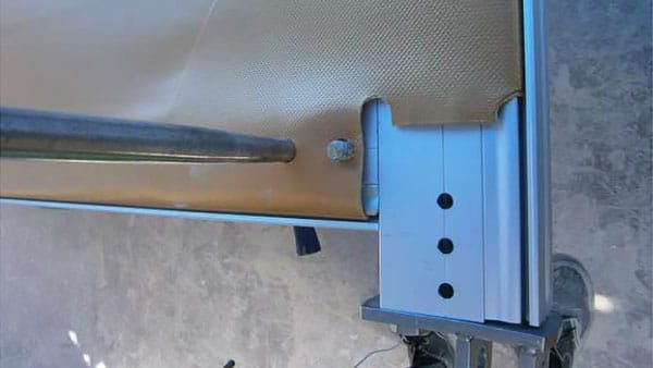
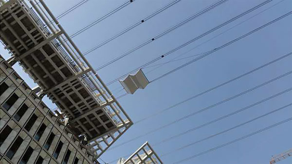
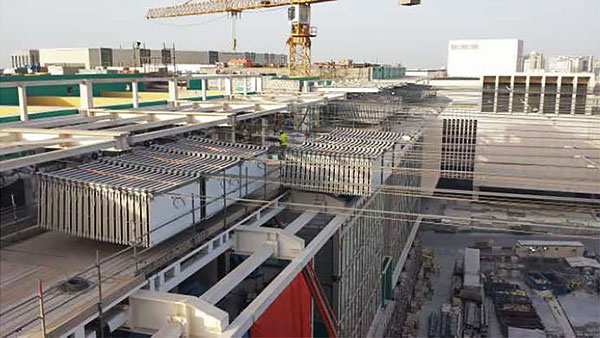
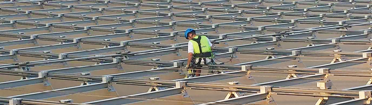
Figure 5 (a) Impression of the membrane panel during installation
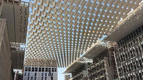
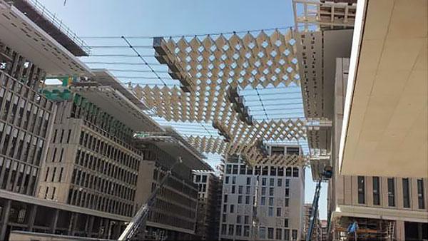
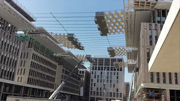
Figure 5 (b-g) Folding process of the retractable roof
Acknowledgments
Client: Msheiireb Properties
Architect: Mossessian & Partners
Structural Engineer: Burns McDonald mit sbp New York
Gerneral Contractor: JV Carillion / QBC
References
[1] Mossessian & Partners. http://www.mossessian.com/mossessian-projects/al-barahat-square/
[2] Law, R. and Underwood K. ‘Msheireb Heart of Doha: an alternative approach to urbanism in the Gulf region’, International Journal of Islamic Architecture 1: 1, (2012), pp. 131–147
[3] Fortmeyer, Russel, Kinetic architecture: designs for active envelopes, The Images Publishing Group Pty Ltd., Victoria, Australia, 2014, pp. 28-29
[4] Peter Oborn (Editor), Al Bahr Towers, The Abu Dhabi Investment Council Headquarters, John Wiley & Sons, West Sussex, Great Britain, 2013
Illustrations
by Thomas Prang, Copyright: Pfeifer Seil- und Hebetechnik GmbH, Memmingen